real time control systems, Modbus RTU devices, low cost I2C I/O modules, free BASIC compiler software, motor controllers, controllers with color graphic displays
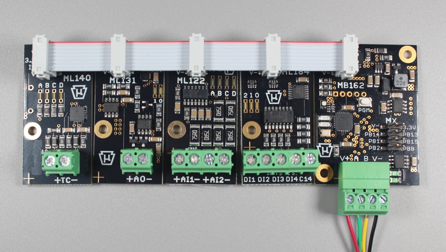
The Microva ML series I2C communication I/O modules are designed to be daisy chain connected side-by-side on a one inch pitch grid using standard eight pin ribbon cable. Custom cables, connectors or expensive crimp tools are not required to connect multiple I/O modules. The image below shows four I2C modules connected to the MB162 controller which is connected to a Modbus RTU network. We call the I2C ribbon cable connector the ML port and many of the Microva BASIC controllers include the ML port so they can directly connect to the I/O modules. The ML port also provides power to the modules including 3.3V for most modern integrated circuits and a higher voltage labeled V+ for devices that require more voltage. Most of the ML series I/O modules include multiple I2C addresses that can be set by cutting traces on the PCB using a hobby knife. A soldering iron is not required to set the address. Several I/O modules, even with the same model number, can be connected on the ML bus providing they have different I2C addresses.
• Microva ML bus I2C communication
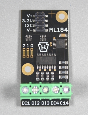
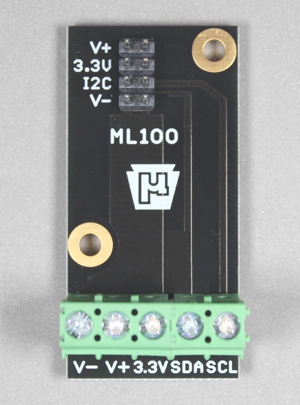
• four opto-isolated inputs
• inputs can source or sink current
• V+ supply voltage is not used
• eight I2C address options
• Microva ML bus I2C communication
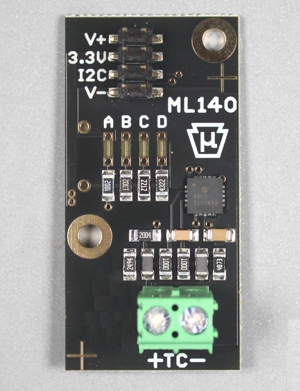
• thermocouple input + fault detection
• reads common thermocouple types
• V+ supply voltage is not used
• four I2C address options
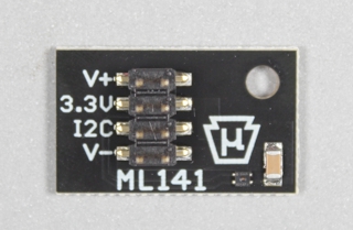
ML141 I2C I/O Module Temperature and Humidity Sensor
• Microva ML bus I2C communication
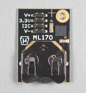
• real time clock with calendar
• accurate temp compensated crystal
• ten year battery backup
• V+ supply voltage is not used
• has a fixed I2C address